STM32F103C8 + Rust: Timer as Downcounting and Center-Aligned Counter
In the previous article, we discussed the Timer peripherals of the STM32F103C8 (Blue Pill) microcontroller and provided an example program using the Timer as an upcounting counter. This article will focus on how to use the STM32F103C8 Timer as a downcounting and center-aligned counter.
As explained in that article, the Timer as a counter will count the ticks based on the defined timer frequency. If we set the timer to a frequency of 1000 Hz (1 kHz), the Timer will count 1000 ticks every second.
Hardware Preparation
The materials used in this tutorial are: the STM32F103C8 (Blue Pill) microcontroller, an ST-Link USB Downloader/Debugger for flashing programs to the STM32F103C8 microcontroller, and jumper wires (female-to-female) to connect the ST-Link to the STM32F103C8 microcontroller.
Timer STM32F103C8 as Downcounting Counter Using Rust
The Timer as a downcounting counter will count down from a specified maximum value to 0 repeatedly. The value in the TIMx_CNT (counter register), which is initially equal to the TIMx_ARR (auto-reload register) value, will continuously decrement by 1 until it reaches 0. As soon as the TIMx_CNT register value reaches 0, it is reset back to the value stored in TIMx_ARR. The following is the timing diagram for the downcounting counter:
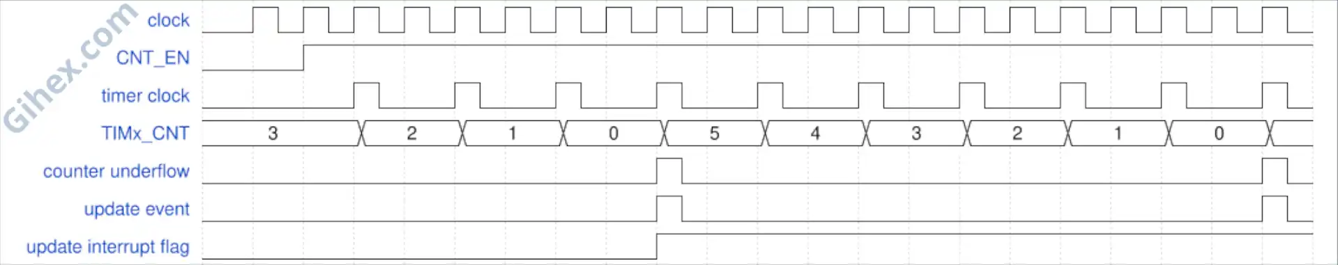
In that image, a prescaler of 2 is used and the TIMx_ARR register value is set to 5. Initially, the TIMx_CNT register value is 5, equal to the TIMx_ARR register; it then decrements by 1 at every timer frequency tick until it reaches 0. Upon reaching 0, the TIMx_CNT register value is reset back to the TIMx_ARR value.
Note: If the Update Interrupt Flag (UIF) is enabled, the UIF register value must be reset manually via the program after the interrupt function is called.
In this tutorial, we will use the Timer 2 (TIM2) peripheral to create a downcounting counter. Keep in mind that, as explained in this article, Timer 2 has a 16-bit resolution.
Programming STM32F103C8 Timer as Downcounting Counter Using Rust
The stm32f1xx_hal crate does not provide a specific method for using the timer as a downcounting counter; however, we can still achieve this by directly accessing the DIR bit of the TIMx_CR1 register.
First, let’s create a new Rust project according to this page. Open the Cargo.toml file and enter the following code to define a new binary executable named timer-counter-down :
1
2[[bin]]
3name = "timer-counter-down"
4path = "src/main.rs"
5test = false
6bench = false
Next, open the src/main.rs file and add the following code:
 1#![no_std]
 2#![no_main]
 3
 4use defmt_rtt as _;
 5use panic_probe as _;
 6
 7use cortex_m_rt::entry;
 8use stm32f1xx_hal::{
 9    flash::FlashExt,
10    pac,
11    prelude::*,
12    rcc::{Config, RccExt},
13    time::Hertz,
14};
Configuring the Rust toolchain to avoid using the standard library and to run the program without an operating system. Next, defining the libraries (crates) being used:
cortex_m_rt: Handles the program startup and defines the entry function where the program begins execution.defmt_rtt: Sends data to the PC/laptop using the Real-Time Transfer protocol.panic_probe: Handles runtime errors and automatically sends error logs to the host PC/laptop.stm32f1xx_hal: Provides an API to access the STM32F103C8 microcontroller peripherals safely.
Inside the main function, add the following code to access the STM32F103C8 peripherals:
1defmt::println!("STM32F103C8 Timer as Counter Downcounting");
2
3let dp = pac::Peripherals::take().unwrap();
Sending a message to the PC/laptop to label the program as a downcounting counter. Next, accessing the STM32F103C8 peripherals.
 1let mut flash = dp.FLASH.constrain();
 2let rcc = dp.RCC.constrain();
 3
 4let clock_config = Config::default()
 5    .use_hse(Hertz::MHz(8))
 6    .sysclk(Hertz::MHz(72))
 7    .hclk(Hertz::MHz(36))
 8    .pclk1(Hertz::MHz(36));
 9
10let mut clocks = rcc.freeze(clock_config, &mut flash.acr);
Accessing the Reset & Clock Control (RCC) and Flash peripherals of the STM32F103C8. Creating the clock configuration by using the High-Speed External Clock ( use_hse ) at 8 MHz, setting the system clock ( sysclk ) to 72 MHz, the Advanced High-performance Bus ( hclk ) to 36 MHz, and Peripheral Bus 1/APB1 ( pclk1 ) to 36 MHz. Finally, applying these configurations to the RCC and Flash peripherals.
1let mut counter = dp.TIM2.counter::<1_000>(&mut clocks);Creating a timer using Timer 2 (TIM2) with a frequency of 1000 Hz (1 kHz). The counter method will automatically calculate the required prescaler value.
Since we configured the High-speed Bus clock ( hclk ) to 36 MHz and the APB1 clock ( pclk1 ) to 36 MHz, the Timer 2 clock frequency is 36 MHz; therefore, the prescaler value is:
Therefore, the TIM2_PSC register value will be 35999.
1unsafe {
2    (*pac::TIM2::ptr()).cr1().modify(|_, w| w.dir().down());
3}
Configuring Timer 2 to perform downcounting. We access the Timer 2 peripheral pointer directly and change the dir bit of the CR1 register to the value 1 by calling the down method.
Pro Tip: When the
dirbit of theCR1register is set to 1, the Timer will perform downcounting. If it is 0, the Timer will perform upcounting.
1counter.start(3000.millis()).unwrap();Starting the downcounting process with a timeout of 3000 ms (3 seconds). The start method will also automatically set the TIM2_ARR register to the corresponding ticks value of the timeout.
Since we are using a timer frequency of 1000 Hz and a timeout of 3000 ms, then:
Therefore, the TIM2_ARR register will contain the value 2999.
 1let mut last_update_time = counter.now();
 2
 3let interval = 1000.millis::<1, 1000>();
 4
 5loop {
 6    let now = counter.now();
 7
 8    if last_update_time.ticks().wrapping_sub(now.ticks()) >= interval.ticks() {
 9        defmt::println!("1000 ms passed | Current counter value: {}", now.ticks());
10        last_update_time = now;
11    }
12}
Creating variables to store the last counter value and the interval for sending messages to the PC/laptop terminal. Here, we use a 1-second (1000 ms) interval. The main program logic will run inside the loop block. First, get the current counter value, then subtract the current value from the stored last counter value. If the result is greater than or equal to the interval, send a message to the PC/laptop terminal and update the last counter value with the current value.
 1#![no_std]
 2#![no_main]
 3
 4use defmt_rtt as _;
 5use panic_probe as _;
 6
 7use cortex_m_rt::entry;
 8use stm32f1xx_hal::{
 9    flash::FlashExt,
10    pac,
11    prelude::*,
12    rcc::{Config, RccExt},
13    time::Hertz,
14};
15
16#[entry]
17fn main() -> ! {
18    defmt::println!("STM32F103C8 Timer as Counter Downcounting");
19
20    let dp = pac::Peripherals::take().unwrap();
21
22    let mut flash = dp.FLASH.constrain();
23
24    let rcc = dp.RCC.constrain();
25
26    let clock_config = Config::default()
27        .use_hse(Hertz::MHz(8))
28        .sysclk(Hertz::MHz(72))
29        .hclk(Hertz::MHz(36))
30        .pclk1(Hertz::MHz(36));
31
32    let mut clocks = rcc.freeze(clock_config, &mut flash.acr);
33
34    let mut counter = dp.TIM2.counter::<1_000>(&mut clocks);
35
36    unsafe {
37        (*pac::TIM2::ptr()).cr1().modify(|_, w| w.dir().down());
38    }
39    counter.start(3000.millis()).unwrap();
40
41    let mut last_update_time = counter.now();
42
43    let interval = 1000.millis::<1, 1000>();
44
45    loop {
46        let now = counter.now();
47
48        if last_update_time.ticks().wrapping_sub(now.ticks()) >= interval.ticks() {
49            defmt::println!("1000 ms passed | Current counter value: {}", now.ticks());
50            last_update_time = now;
51        }
52    }
53}
Connect the STM32F103C8 microcontroller to your PC/laptop using the ST-Link USB Downloader/Debugger, then run the program using the command cargo run --bin timer-counter-down in the terminal. The following is the result:
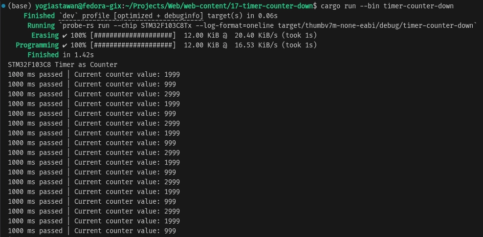
In these results, it can be seen that the initial value of the TIM2_CNT register is 2999, which then decreases by 1 for every timer frequency tick until it reaches 0. Since we are using a 1000 ms interval, the counter value sent to the PC/laptop will decrease by 1000 at each interval. Upon reaching 0, the TIM2_CNT register value will be reset to the TIM2_ARR value.
Timer STM32F103C8 as Center-Aligned Counter Using Rust
A timer configured as a center-aligned counter will count from 0 up to a specified maximum value (upcounting), and after reaching that maximum, it continues by counting back down to 0 (downcounting). When the timer starts, the TIMx_CNT (Counter Register) value initially 0, increments by 1 for every timer tick until it equals the TIMx_ARR (Auto-Reload Register) value. Upon reaching the TIMx_ARR value, the counter value then decrements by 1 for every timer tick. The following is the timing diagram for a center-aligned counter:
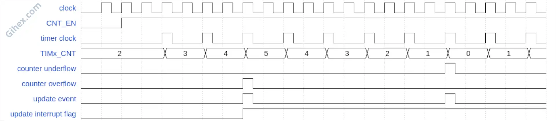
In that image, the timer uses a prescaler of 2, so every 2 timer clock ticks equal 1 timer tick. The diagram also uses a TIMx_ARR value of 5. The TIMx_CNT initially starts at 0 and increments by 1 for every timer frequency tick until its value equals TIMx_ARR. Once the TIMx_CNT value equals TIMx_ARR, it decrements by 1 for every timer frequency tick until it reaches 0. This process repeats continuously.
In this tutorial, we will continue to use Timer 2 and access its registers directly, as the stm32f1xx_hal crate does not provide a built-in method for utilizing a center-aligned counter.
Programming STM32F103C8 Timer sebagai Center-Aligned Counter Using Rust
First, let us define a new binary executable named timer-counter-center in the Cargo.toml file.
1[[bin]]
2name = "timer-counter-center"
3path = "src/counter_center_aligned.rs"
4test = false
5bench = false
Create the file src/counter_center_aligned.rs and then add the following code:
 1#![no_std]
 2#![no_main]
 3
 4use defmt_rtt as _;
 5use panic_probe as _;
 6
 7use cortex_m_rt::entry;
 8use stm32f1xx_hal::{
 9    flash::FlashExt,
10    pac,
11    prelude::*,
12    rcc::{Config, RccExt},
13    time::Hertz,
14};
This is the same code as the previous program, used to configure the Rust compiler and define the libraries being utilized.
 1defmt::println!("STM32F103C8 Timer as Counter Center Aligned");
 2
 3let dp = pac::Peripherals::take().unwrap();
 4
 5let mut flash = dp.FLASH.constrain();
 6
 7let rcc = dp.RCC.constrain();
 8
 9let clock_config = Config::default()
10    .use_hse(Hertz::MHz(8))
11    .sysclk(Hertz::MHz(72))
12    .hclk(Hertz::MHz(36))
13    .pclk1(Hertz::MHz(36));
14
15let mut clocks = rcc.freeze(clock_config, &mut flash.acr);
Just like the previous program, this is used to access all STM32F103C8 peripherals and configure the clock.
1let mut counter = dp.TIM2.counter::<1_000>(&mut clocks);
2
3unsafe {
4    (*pac::TIM2::ptr())
5        .cr1()
6        .modify(|_, w| w.cms().center_aligned1());
7}
Accessing the Timer 2 (TIM2) peripheral while simultaneously configuring its frequency to 1000 Hz (1 kHz). Next, we access the Timer 2 pointer and set the CMS (Center-aligned Mode Selection) bits of the CR1 register to the value 0x01 ( center_aligned1 ). Since we are using a 36 MHz timer clock frequency and setting the timer frequency to 1000 Hz, the TIM2_PSC register value will be 35999. The calculation is the same as in the downcounting counter section.
Note:
CMSis used to configure the center-aligned counter mode. When its value is 0x00, center-aligned mode is disabled. Based on theCMSvalue, there are three center-aligned counter modes, which are:
- With the value 0x01 (
center_aligned1): The Update Interrupt Flag is set to 1 when the counter is in the downcounting phase.- With the value 0x10 (
center_aligned2): The Update Interrupt Flag is set to 1 when the counter is in the upcounting phase.- With the value 0x11 (
center_aligned3): The Update Interrupt Flag is set to 1 when the counter is in both the upcounting and downcounting phases.
1counter.start(3000.millis()).unwrap();Starting the counter process with a 3000 ms timeout. Since we set the timer frequency to 1000 Hz, the TIM2_ARR register value will be 2999. The calculation is the same as in the downcounting counter section.
 1let mut last_update_time = counter.now();
 2
 3let interval = 500.millis::<1, 1000>();
 4
 5loop {
 6    let now = counter.now();
 7
 8    let delta = last_update_time.ticks().abs_diff(now.ticks());
 9
10    if delta >= interval.ticks() {
11        match now.ticks() > last_update_time.ticks() {
12            true => defmt::println!("Upcounting"),
13            false => defmt::println!("Downcounting"),
14        }
15        defmt::println!(
16            "{} ms passed | Current counter value: {}",
17            interval.to_millis(),
18            now.ticks()
19        );
20        last_update_time = now;
21    }
22}
Creating variables to store the last counter value and the interval for checking the counter value. Then, inside the loop block, we calculate the absolute difference between the last stored counter value and the current counter value. If the difference is greater than or equal to the interval value, we compare the current counter value with the last stored value. If the current counter value is greater than the last stored value, it indicates an upcounting process; otherwise, it is a downcounting process. Finally, send the current counter value to the PC/laptop terminal and update the last counter value with the current value.
 1#![no_std]
 2#![no_main]
 3
 4use defmt_rtt as _;
 5use panic_probe as _;
 6
 7use cortex_m_rt::entry;
 8use stm32f1xx_hal::{
 9    flash::FlashExt,
10    pac,
11    prelude::*,
12    rcc::{Config, RccExt},
13    time::Hertz,
14};
15
16#[entry]
17fn main() -> ! {
18    defmt::println!("STM32F103C8 Timer as Counter Center Aligned");
19
20    let dp = pac::Peripherals::take().unwrap();
21
22    let mut flash = dp.FLASH.constrain();
23
24    let rcc = dp.RCC.constrain();
25
26    let clock_config = Config::default()
27        .use_hse(Hertz::MHz(8))
28        .sysclk(Hertz::MHz(72))
29        .hclk(Hertz::MHz(36))
30        .pclk1(Hertz::MHz(36));
31
32    let mut clocks = rcc.freeze(clock_config, &mut flash.acr);
33
34    let mut counter = dp.TIM2.counter::<1_000>(&mut clocks);
35
36    unsafe {
37        (*pac::TIM2::ptr())
38            .cr1()
39            .modify(|_, w| w.cms().center_aligned1());
40    }
41
42    counter.start(3000.millis()).unwrap();
43
44    let mut last_update_time = counter.now();
45
46    let interval = 500.millis::<1, 1000>();
47
48    loop {
49        let now = counter.now();
50
51        let delta = last_update_time.ticks().abs_diff(now.ticks());
52
53        if delta >= interval.ticks() {
54            match now.ticks() > last_update_time.ticks() {
55                true => defmt::println!("Upcounting"),
56                false => defmt::println!("Downcounting"),
57            }
58            defmt::println!(
59                "{} ms passed | Current counter value: {}",
60                interval.to_millis(),
61                now.ticks()
62            );
63            last_update_time = now;
64        }
65    }
66}
Run the program using the command cargo run --bin timer-counter-center in the terminal. The following is the result:
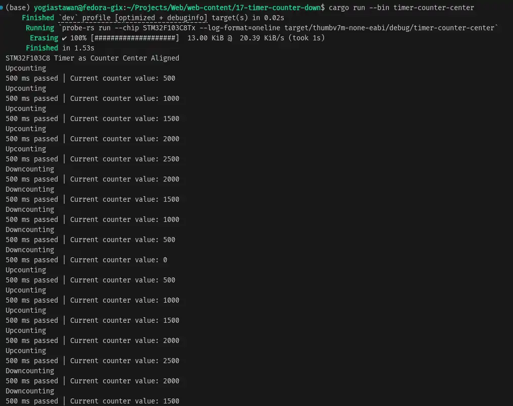
In the results, it can be seen that the counter increments from 0 to the TIM2_ARR value (2999). Then, after reaching the TIM2_ARR value, the counter decrements down to 0. This process repeats continuously.
Issues & Source Code
The stm32f1xx_hal crate does not provide methods to utilize the counter in downcounting or center-aligned modes. However, we can still achieve this by accessing the timer registers directly to configure the DIR and CMS bits.
If you encounter any issues or wish to provide feedback and suggestions, please contact us through the contact page.
The program’s source code used in this tutorial can be accessed at the Github repository.